
|
CGAL 6.2 - 3D Triangulation Data Structure
|
Loading...
Searching...
No Matches
|
CGAL 6.2 - 3D Triangulation Data Structure
|
A geometric triangulation has two aspects: the combinatorial structure, which gives the incidence and adjacency relations between faces, and the geometric information related to the position of vertices.
CGAL provides 3D geometric triangulations in which these two aspects are clearly separated. As described in Chapter 3D Triangulations, a geometric triangulation of a set of points in \( \mathbb{R}^d\), \( d\leq 3\) is a partition of the whole space \( \mathbb{R}^d\) into cells having \( d+1\) vertices. Some of them are infinite, they are obtained by linking an additional vertex at infinity to each facet of the convex hull of the points (see Section Representation). The underlying combinatorial graph of such a triangulation without boundary of \( \mathbb{R}^d\) can be seen as a triangulation of the topological sphere \( S^d\) in \( \mathbb{R}^{d+1}\).
This chapter deals with 3D-triangulation data structures, meant to maintain the combinatorial information for 3D-geometric triangulations. The reader interested in geometric triangulations of \( \mathbb{R}^3\) is advised to read Chapter 3D Triangulations.
In CGAL, a 3D triangulation data structure is a container of cells ( \( 3\)-faces) and vertices ( \( 0\)-faces).
Following the standard vocabulary of simplicial complexes, an \( i\)-face \( f_i\) and a \( j\)-face \( f_j\) \( (0 \leq j < i \leq 3)\) are said to be incident in the triangulation if \( f_j\) is a (sub)face of \( f_i\), and two \( i\)-faces \( (0 \leq i \leq 3)\) are said to be adjacent if they share a common incident (sub)face.
Each cell gives access to its four incident vertices and to its four adjacent cells. Each vertex gives direct access to one of its incident cells, which is sufficient to retrieve all the incident cells when needed.
The four vertices of a cell are indexed with 0, 1, 2 and 3. The neighbors of a cell are also indexed with 0, 1, 2, 3 in such a way that the neighbor indexed by \( i\) is opposite to the vertex with the same index (see Figure 49.1).
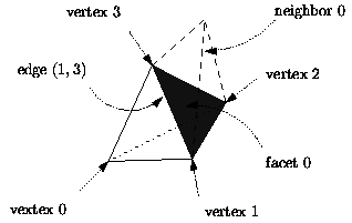
Figure 49.1 Representation.
Edges ( \( 1\)-faces) and facets ( \( 2\)-faces) are not explicitly represented: a facet is given by a cell and an index (the facet i of a cell c is the facet of c that is opposite to the vertex of index i) and an edge is given by a cell and two indices (the edge (i,j) of a cell c is the edge whose endpoints are the vertices of indices i and j of c).
Degenerate Dimensions
As CGAL explicitly deals with all degenerate cases, a 3D-triangulation data structure in CGAL can handle the cases when the dimension of the triangulation is lower than 3.
Thus, a 3D-triangulation data structure can store a triangulation of a topological sphere \( S^d\) of \( \mathbb{R}^{d+1}\), for any \( d \in \{-1,0,1,2,3\}\).
Let us give, for each dimension, the example corresponding to the triangulation data structure having a minimal number of vertices, i.e. a simplex. These examples are illustrated by presenting their usual geometric embedding.
dimension 3. The triangulation data structure consists of the boundary of a 4-dimensional simplex, which has 5 vertices. A geometric embedding consists in choosing one of these vertices to be infinite, thus four of the five 3-cells become infinite: the geometric triangulation has one finite tetrahedron remaining, each of its facets being incident to an infinite cell. See Figure 49.2.
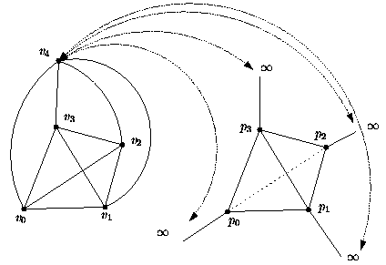
Figure 49.2 4D simplex and a 3D geometric embedding.
dimension 2. We have 4 vertices forming one 3-dimensional simplex, i.e. the boundary of a tetrahedron. The geometric embedding in the plane results from choosing one of these vertices to be infinite, then the geometric triangulation has one finite triangle whose edges are incident to the infinite triangles. See Figure 49.3.
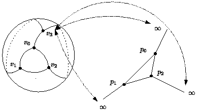
Figure 49.3 3D simplex and a 2D geometric embedding.
dimension 1. A 2-dimensional simplex (a triangle) has 3 vertices. The geometric embedding is an edge whose vertices are linked to an infinite point. See Figure 49.4.
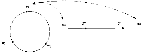
Figure 49.4 2D simplex and a 1D geometric embedding.
The last three cases are defined uniquely:
Note that the notion of infinite vertex has no meaning for the triangulation data structure. The infinite vertex of the geometric embedding is a vertex that cannot be distinguished from the other vertices in the combinatorial triangulation.
The same cell class is used in all cases: triangular faces in 2D can be considered as degenerate cells, having only three vertices (resp. neighbors) numbered \( (0,1,2)\); edges in 1D have only two vertices (resp. neighbors) numbered \( 0\) and \( 1\).
The implicit representation of facets (resp. edges) still holds for degenerate ( \( < 3\)) dimensions : in dimension 2, each cell has only one facet of index 3, and 3 edges \( (0,1)\), \( (1,2)\) and \( (2,0)\); in dimension 1, each cell has one edge \( (0,1)\).
Validity
A 3D combinatorial triangulation is said to be locally valid iff the following is true:
(a) When a cell \( c\) has a neighbor pointer to another cell \( c'\), then reciprocally this cell \( c'\) has a neighbor pointer to \( c\), and \( c\) and \( c'\) have three vertices in common. These cells are called adjacent.
(b) The cells have a coherent orientation: if two cells \( c_1\) and \( c_2\) are adjacent and share a facet with vertices \( u,v,w\), then the vertices of \( c_1\) are numbered \( (v_0^1 = u, v_1^1 = v, v_2^1 = w, v_3^1)\), and the vertices of \( c_2\) are numbered \( (v_0^2 = v, v_1^2 = u, v_2^2 = w, v_3^2)\), up to positive permutations of \( (0,1,2,3)\). In other words, if we embed the triangulation in \( \mathbb{R}^3\), then the fourth vertices \( v_3^1\) and \( v_3^2\) of \( c_1\) and \( c_2\) see the common facet in opposite orientations. See Figure 49.5.
The set \( \sigma\) \( _4\) of permutations of \( (0,1,2,3)\) has cardinality 24, and the set of positive permutations \( A_4\) has cardinality 12. Thus, for a given orientation, there are up to 12 different orderings of the four vertices of a cell. Note that cyclic permutations are negative and so do not preserve the orientation of a cell.
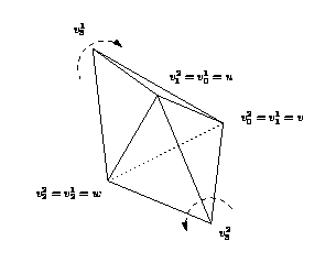
Figure 49.5 Coherent orientations of two cells (3-dimensional case).
The method Triangulation_data_structure_3::is_valid() method checks the local validity of a given triangulation data structure.
The 3D-triangulation data structure class of CGAL, Triangulation_data_structure_3, is designed to be used as a combinatorial layer upon which a geometric layer can be built [1]. This geometric layer is typically one of the 3D-triangulation classes of CGAL: Triangulation_3, Delaunay_triangulation_3 and Regular_triangulation_3. This relation is described in more details in Chapter 3D Triangulations, where the Section Software Design explains other important parts of the design related to the geometry.
We focus here on the design of the triangulation data structure (TDS) itself, which the Figure 49.6 illustrates.
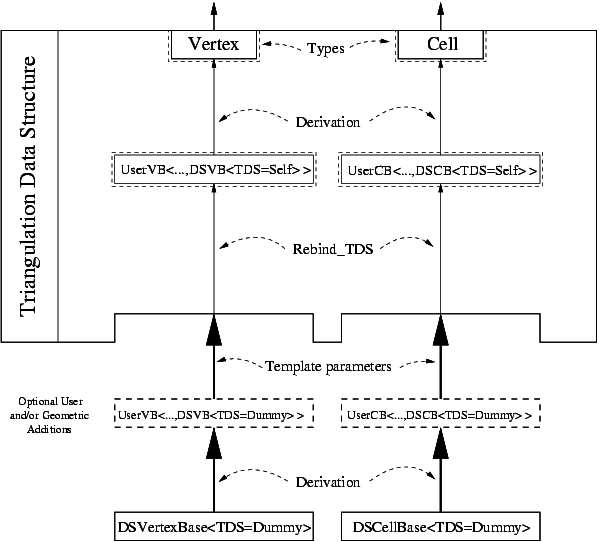
Figure 49.6 Triangulation Data Structure software design.
In order for the user to be able to add his own data in the vertices and cells, the design of the TDS is split into two layers:
In the bottom layer, the (vertex and cell) base classes store elementary incidence and adjacency (and possibly geometric or other) information. These classes are parameterized by the TDS which provides the handle types. (They can also be parameterized by a geometric traits class or anything else.) A vertex stores a Cell_handle, and a cell stores four Vertex_handles and four Cell_handles.
The user has several ways to add his own data in the vertex and cell base classes used by the TDS. He can either:
Triangulation_vertex_base_with_info_3 and Triangulation_cell_base_with_info_3, which allow to add one data member of a user provided type, and give access to it. Triangulation_ds_vertex_base_3, and Triangulation_ds_cell_base_3 (or the geometric versions typically used by the geometric layer, Triangulation_vertex_base_3, and Triangulation_cell_base_3). TriangulationCellBase_3 and TriangulationVertexBase_3. Since adjacency relations are stored in the vertices and cells, it means that the vertex and cell base classes have to be able to store handles (an entity akin to pointers) to their neighbors in the TDS. This in turns means that the vertex and cell base classes have to know the types of these handles, which are provided by the TDS. So in a sense, the base classes are parameterized by the TDS, and the TDS is parameterized by the vertex and cell base classes ! This is a cycle which cannot be resolved easily.
The solution that we have chosen is similar to the mechanism used by the standard class std::allocator: the vertex and cell base classes are initially given a fake or dummy TDS template parameter, whose unique purpose is to provide the types that can be used by the vertex and cell base classes (such as handles). Then, inside the TDS itself, these base classes are rebound to the real TDS type, that is we obtain the same vertex and cell base classes, but parameterized with the real TDS instead of the dummy one. Rebinding is performed by a nested template class of the vertex and cell base classes (see code below), which provides a type which is the rebound vertex or cell base classIt is logically equivalent to a mechanism that does not exist yet in the C++ language: template typedef or template aliasing.
Here is how it works, schematically:
When derivation is used for the vertex or cell base classes, which is the case at the geometric level with Triangulation_vertex_base_3, then it gets slightly more involved because its base class has to be rebound as well:
The third template parameter of Triangulation_data_structure_3 is ConcurrencyTag. It enables the use of a concurrent container (Concurrent_compact_container) to store vertices and cells. If it is Parallel_tag, then create_vertex(), create_cell(), delete_vertex() and delete_cell() can be called concurrently.
The following example shows how to construct a 3D triangulation data structure by inserting vertices.
Example: TDS_3/tds.cpp
This example program illustrates how to setup a 2D and a 3D triangulation data structures whose vertices respectively store vertex handles of the other one.
Example: TDS_3/linking_2d_and_3d.cpp
Monique Teillaud introduced the triangulation of the topological sphere \( S^d\) in \( \mathbb{R}^{d+1}\) to manage the underlying graph of geometric triangulations and handle degenerate dimensions [2].
Sylvain Pion improved the software in several ways, in particular regarding the memory management.
In 2013, Clément Jamin added the ability to create/delete vertices and cells in parallel. This feature is used by the parallel triangulation.